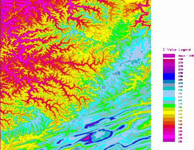
SurfMate is a digital terrain modelling and earthworks design solution giving the designer many enhanced features for use in Digital Terrain Modelling and Earthworks design completely integrated with AutoCAD. TECHNoCAD have put great effort into packing as many useful options as possible into the software to make it the most valuable add-on to AutoCAD available to the DTM modeller today. SurfMate has taken the lead in DTM software running in the World’s No.1 CAD package – AutoCAD. With its lightning speed with surfaces of unlimited numbers of points and multiple surfaces in memory, SurfMate is used by mappers, surveyors, engineers, geologists and environmentalists world-wide.
SurfMate now takes digital terrain modelling into the 21st century making repetitive and time consuming tasks as easy as pressing a button – literally! Now you can design a building terrace with automatically optimised cut and fill volumes, draw the embankment batter slope lines automatically and label the terrace elevations automatically to produce a 3D model of the terrace as well as a working drawing in 3 simple operations. These are just some of the features!
Seamless Integration
SurfMate is seamlessly integrated with AutoCAD. By utilising the same menu interface in AutoCAD for all design products reduces the learning curve when it comes to executing designs and linking DTM modelling with civil engineering type design. All software programs can be interlinked using AutoCAD as the common graphics engine with no transfers to external programs.
Documentation and On-line help
There is a fully featured extensive on-line help which describe all the options from installation to detailed use of the various features.
Available now!
Users of earlier versions of SurfMate can access the new version by purchasing an upgrade. If you are currently on a software maintenance agreement, then you can obtain the latest version free of charge.
Consider these features available in this amazing product and place your orders today:
Application examples
SurfMate can be used in a variety of applications including:
- Topography
- Slope analysis
- 3D flowlines
- Thickness maps
- Bathymetry
- Contaminant modelling
- Cross sections and profiles
- Visibility analysis
- Lighting analysis
- Building terrace design
- Preliminary road route planning (use RoadMate for full road design)
- Faulted geology
- Mine planning
- Mining engineering
- Mining geology
- Golf course design
- Site visualization
Topography
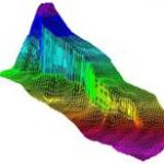 SurfMate generates contours or surface meshes for topography starting from x, y, z files, digital elevation models or extracted drawing entities, such as spot elevations or contour polylines. 3D breaklines defining elements such as building pad perimeters, roads or geologic faults may optionally be used. Contours may be based on a TIN, grid or triangulated grid.
Contouring directly on the TIN (Triangulated Irregular Network) is common in civil site design. Contouring on the grid allows for smooth curved surfaces between your data points. Contouring on the triangulated grid (unique to SurfMate) allows both smooth curving surfaces and exact honouring of breaklines. Optional contour line indexing, annotation, hachuring, and colour options are available.
Slope Analysis
SurfMate can display your surface coloured by surface slope in percent or degrees complete with coloured legend showing the slope breakdown. Iso-slope contours may be created and draped onto the surface in 3D. Creating slope analysis maps is quick, easy and flexible.
3D Flowlines
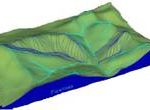 3D flowlines represent the 3D path a drop of water would take if placed on the surface. A flowline runs perpendicular to a contour line. Flowlines are a great way to check drainage designs or delineate watersheds.
Creating Thickness Maps
Thickness (isopach) maps represent the thickness between two surfaces. For example, an isopach between the top and base of a coal seam would be used for mapping the distribution of the coal seam. A thickness map between existing and design topography is the basis for cut and fill volumes. Thickness maps are created by subtracting two elevation surfaces, such as an existing and a design topography, or the top and base of a geologic unit. SurfMate includes much more than just subtraction: over 30 surface-to-surface mathematical operations are included, including trend analysis and slope analysis.
Contouring Bathymetry
Many private firms and government agencies to map coastal and navigable waterways, reservoirs and rivers use SurfMate. Profiles, cross-sections, water and sediment volumes are generated quickly and easily.
Modelling Contaminants
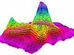 Modelling contaminant distribution with SurfMate uses the Kriging capability of the program. Interactive variogram design allows you to create custom semi-variograms to match the transport characteristics of the contaminant – stratigraphy combination.
Logarithmic contours may be used or irregular contours based on specific contaminant thresholds may be generated. Several maps may be combined to show the relationship between the contaminant and bedrock topography, stratigraphy or ground water surfaces.
Creating Sections
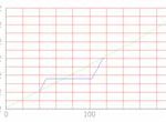 Longitudinal sections and cross-sections may be created along any arbitrary line or polyline paths. Use the centreline of a road or stream to create a 2D graph of elevation versus distance.
Create a profile of existing topography along your proposed centreline, then draw your design vertical alignment right on the 2D profile and reapply it to the design centreline to create a 3D centreline polyline to your exact design. Great for preliminary road design or open channel hydraulics design.
Computing Volumes
Rapid, accurate volumetric computation is a strength of SurfMate. All volumes are prismoidal volumes of a TIN, grid or triangulated grid representing your surface. The Area Volume command lets you calculate the volumes within any number of closed area polylines. Supply one surface representing thickness or two surfaces representing the top and base of a unit (or existing and design topography) and volumes are calculated and reported with cut, fill and net volumes for each area, plus the grand total.
Surface mining engineers use area volumes to calculate overburden and product volumes under hundreds of removal polygons in one pass. Site designers use area volumes for cut/fill calculations for different parts of the design area. The resulting thickness map is always preserved so you may contour the cut/fill or isopach map.
Visibility Analysis
Sight lines are important in site planning, environmental remediation and transmission tower placement. Choose a viewpoint location and SurfMate will display a visibility analysis by colouring the topographic surface by angle of incidence where it is visible and indicating areas, which are not visible from that viewpoint.
Lighting Analysis
Surface lighting may be analysed by supplying a light location, and then the displaying the surface coloured based on the angle of incidence of light striking the surface.
Designing Platforms/Terraces
Creating building terraces set into the existing terrain is painless. If the terrace is slightly sloping, draw your outline with a polyline and then use “grade polyline to a plane” and simply show SurfMate your required direction of fall and input the value of the grade. Your polyline is instantly updated in 3D!
Supply the cut slope and fill slope angles and SurfMate’s intersect slope command will project the slopes from your pad perimeter and calculate the head of the cut and the toe of the fill and draw the resulting daylight line in 3D.

Create a new design surface by selecting the daylight and perimeter lines as break lines and your done. Use SurfMate’s optimise terrace routine to have your design with balanced cut/fill or even with a designated amount of excess cut/fill material. Take into account material bulking factors.

Complex earthworks designs can be accommodated where you require varying earthworks side-slopes. Slopes can be transitioned using linear or spline methodology.
Preliminary Road Route Planning
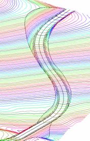 Tools are included for basic preliminary road design (use in conjunction with RoadMate for detailed road design). Starting with the proposed 2D-road centreline in plan view, drape it on existing topography and make a quick 2D longitudinal section/profile of the existing ground along the road. Draw your approximate design vertical alignment right on the longitudinal profile.
Use vertical align to apply your preliminary vertical alignment back to your 3D-road centreline, resulting in a 3D centreline of your road. Use “apply section” to use a preliminary cross-section template of your roadway to create the breaklines for the road, including the cut and fill daylight lines.
Faulted Geology
Complex faulting may be accurately modelled using SurfMate. Faults may be drawn in as 2D polylines and placed in 3D using the extrapolate command which extrapolates the local gradients from the wells within the fault block. Vertical position and throw may be analysed and adjusted using the drape, flatten and vertical align commands. Faulted surfaces may be used with cross-sections and volumetrics. Surfaces may be created representing the fault itself and then intersected with a stratigraphic surface to solve for the 3D-fault trace.
Mine Planning
SurfMate can model surface topography, subsurface geology and changing surface mine configuration to calculate reserves, overburden and product volumes and map quality data. Structure and thickness maps can be quickly calculated and used together with the area volumes command to compute product and overburden volumes for hundreds of irregular uncover and removal polygons in one pass. The “intersect slope” command allows rapid design of highwall intersections or lift configuration for a tailings pile. Stockpile volumes may be reported in any volume units you require.
Mining Engineering
Reservoir modelling including structure, isopach, porosity, permeability and saturation maps may be created from well bore data or from the technical committee’s contour polylines. SurfMate’s surface operations lets you model each parameter independently and then calculate the hydrocarbon pore volume using surface-to-surface math. Need each parameter by lease tract? No problem, use the area volume command, supply closed polylines for the lease outlines and SurfMate will calculate hydrocarbon pore volume, net pay, or any other parameter, tract by tract. Put your planimeter in the museum. Supply your conversion factors and you can report your volumes in stock tank barrels. Need to fill your reservoir simulation software and view the results? SurfMate’s open architecture allows you to sample your reservoir on any spacing (or an irregular spacing) and export the parameter values to your simulation model. Import and view your simulation results graphically.
Mining geology
SurfMate handles large geological data sets with ease. Whether you are mapping a prospect with 20 boreholes or a basin with 40,000 boreholes, SurfMate can build your map in less than 30 seconds. Structure maps, faulted structure maps and isopach maps with complex zero lines may all be created and modified quickly. Any geological interpretation starts with the raw data and builds upon it using the power of the mapping algorithms together with the guidance from the experienced explorationist to converge on the best answer. SurfMate is designed for rapid iteration as you build and modify your maps. Powerful surface-to-surface math allows you to quickly compute resulting structure maps from an isopach and underlying structure maps. Balanced isopach maps, analogous to balanced cross section keep you honest. Curvature analysis allows for mapping fractured reservoirs. Trend surface and residual methods are built in.
Golf Course Design
SurfMate is widely used in golf course design and visualization. Smooth curvature together with breaklines and boundaries of arbitrary complexity allows the designer to construct, analyse and visualize the most demanding courses. SurfMate can output directly to rendering packages, such as 3D Studio, for fly over visualization. Bunkers, greens and fairways may be exported individually for ease of materials application.
Site Visualisation
 Once your design nears completion, SurfMate allows you to “stand” anywhere on the surface and look around in perspective view.
The surface view command lets you specify camera height and camera lens for perspective views from close-up to aerial perspectives. Complex surfaces may be partitioned based upon surface material for rendering and resampled at an optimum face count for the rendering package. You will never find a flipped or missing face in a SurfMate mesh.
SurfMate Utilities
SurfMate is packed full of useful features which can even be used for normal AutoCAD draughting or other design packages in AutoCAD:
- Draw Co-ordinate Grid (Lo or Cartesian) using grid lines or ‘crosses’; updated with new dialogue box input
- Reduce and plot manual tache fieldbook data
- Draw Selected Points with Descriptions – modified with dialogue box input, filters for descriptions and high speed reading. Plot your survey points with textual descriptions and elevations! Great for checking out your survey prior to constructing a surface
- Draw breaklines from a file to check them before adding them to a surface. Ever had the problem where you have been supplied breakline data that you want to check for errors before using ‘Break extract’ in QuickSurf?
- Draw Point (Z interpolated from a surface)
- Draw Point (Z interpolated from 2 points)
- Copy selected entities to layer (& make / set layer)
More…
- Auto connect points with a 3D polyline for joining breakline points etc.
- Decurve contour polylines globally
- Weed out points (too dense data)
- Weed out polylines (vertices to close and wasteful)
- Label contours auto-line with user definable text colours and auto-zoom while labelling. Enables you to have complete control over labelling colours.
- Write draped 3D polyline section 2D distances and levels to a file
- Height/Volume calculation from contours of an area for dams, stockpiles etc.
- Export entity XYZ data from your drawing to another survey system, such as Lo or other UCS, to a file
SurfMate Earthworks
SurfMate has earthworks design features to automate the design and draughting process which are normally time consuming, especially when optimising earthworks!
- Advanced Polyline Editor – step through the vertices of a 2D or 3D polyline and change X,Y, or Z values in real-time! Works on all
- polylines, including lightweight polylines
- Grade polylines to a plane defined by a known level and a grade in a defined direction.
- Polyline Modeller to grade polylines from a known level with a given grade or between 2 known levels.
- Optimised terrace design with a resulting merged terrace with the original ground surface
- Label 3D polyline elevations with text in a box automatically for terraces, parking areas etc.
- Draw batter slope lines between breaklines with user definable spacing and proportions for roads embankments, terrace embankments etc.
- Calculate dump / stockpile volume within a 3D toe polyline
Toolbox
Toolboxes in any CAD environment are the answer to saving time and increasing productivity. Here are some of the features in the toolbox:
Set
- Set Layer / Colour / Linetype by picking an entity
- Surveyor’s customised linetypes including fence, rail, telephone line etc. etc.
Layer control
- Show an entity’s layer by picking
- Turn off / freeze layer by picking
- Freeze except picked entity’s layer
- Turn on / off / thaw all layers
- Delete all entities on picked entity’s layer
- Save the layer dialogue status to a file – includes Paperspace, Modelspace and Xrefs!
- Restore the layer dialogue status from a file!
Text
- Change text globally (find & replace etc.)
- Change text heights by a scale factor when changing plotting scale
- Round off decimal places of text values
- Add/subtract values to text
- Import text from a file
- Underline selected picked text
- Auto incrementing text numbers (e.g. stand No’s)
- Change entity properties by picking
- Layer/Layer (keeping colour bylayer)
- Colour/Linetype
Draw
- Co-ordinate table of inserted blocks; creates a co-ordinate data table as you pick your points – great for ‘setting-out’ data tables. User selectable colours for table lines etc.
- Automatically update values in the co-ordinate table when points are moved or erased!
- Pointer block with attributes as block co-ordinates
Construct
- Offset to current layer
- Multiple offset of parallel lines
- Trim all objects inside a polyline
- Trim all objects outside a polyline
- Measure length of picked line, polyline circle or arc
- Angle of line (both directions)
Additional SurfMate features
Multiple Document Environment
SurfMate will operate in the Multiple Document Environment (MDE). Surfaces are visible and available across drawings.
Leader with ‘Z’
Allows you to pick a point and then have the elevation of that point written as the text in a Mtext leader. The text is also updated if the point object is moved in the ‘z’ direction, for example by draping onto a different surface.
Make 2D of any Objects
Allows you to ‘squash’ all objects in a drawing (or a selection set), so that all the elevations are set to zero.
MultiJoin to 2D Polyline
Gives you the ability to join Arcs, Lines, Polylines and Lightweight polylines to form a new Lightweight polyline. Allows you to set a tolerance or ‘fuzzy’ factor, so that you can now join those Lines and Arcs that have been filleted where AutoCAD’s ‘Pedit’ command refuses!
Join 3D Polylines
This utility has been enhanced. You can now set a tolerance or ‘fuzzy’ factor when you want to join 3D polylines. This is great for connecting up segments of a toe-line when modelling earthworks. Speed has also been increased. In addition, you can now join Lines and 2D Polylines together to make a 3D polyline.
Menu Restructuring
The SurfMate menu has now been re-structured into a more logical order. For example, all the options that have something to do with designing have now been grouped together under ‘Design’. Utilities for performing annotation of your drawing have now been grouped together under ‘Annotation’.
Survey Joins – distances and bearings
Allows you to label joins with distance annotation and bearing annotation. Bearing annotation can be set for the cartesian co-ordinate system or for the RSA Lo co-ordinate system. Works for individual Lines or segments of polylines (no need to explode polylines). Great for your cadastral survey plans.
‘Weed’ polyline vertices
Designed explicitly for sorting out contour lines where the contour lines have more vertices than required to define their shape. This is very common where contours have been digitised using point streaming or similar techniques. The utility allows you to set a minimum distance between vertices, together with a minimum deflection angle at a vertex. This allows you to have far more control over your vertex weeding operations, as you will always maintain the shape of the contour, but with less defining vertices. Using this technique, drawing sizes that contain large numbers of contours can now be drastically reduced.
TechTip
Enables you to move the cursor over a drawing containing survey points and have a tooltip display the elevation of the Point object. In addition you can configure the tooltip to also display the point description via a ‘right-click’ context sensitive menu.
Toolbars
Lots of new Toolbars now available.
Erf/Stand/Plot numbering
This existing routine has been enhanced with a dialogue box where you can now select a prefix for your annotation.
Draw Co-ordinate Grid
This ‘old-favourite’ routine has had some enhancements. You can now add a Constant to the value of a co-ordinate (X and Y if you like), and you have a choice of labeling formats.
Scale Blocks by a scale factor
Allows you to scale any Block by a scale factor. Great for when you want to plot your drawing at a different scale, but want the size of your blocks to remain constant on the print.
Co-ordinate data table generator
This powerful utility has been enhanced. You can now choose between generating either a 2D (X,Y or Y, X) or a 3D table (X,Y,Z or Y, X, Z). Lineweights for the border and internal lines for the table are user selectable, as well as colours (full 256 colour range now available). Once you have decided on your settings, you can store them away in a configuration file, ready for retrieving at a later stage. Of course, when setting out points are moved, you can have your table automatically update to reflect the new co-ordinate positions and the elevations. Great for tabulating parking lot coordinates and levels; simply define where you want your setting-out positions, then drape the setting-out defining blocks onto your SurfMate surface and update your table. Use a similar procedure for complex earthworks design.
Convert 2D lines to 3D Breaklines
Extremely useful utility for solving the problem of turning 2D lines into 3D breaklines. If you receive survey data from a source that gives you the points in 3D, but breaklines connecting points are shown in 2D, you would previously need to laboriously take each line and snap it’s end to the nearest 3D survey point. With this utility, you can achieve this automatically, and also be told which 2D lines have no associated 3D point. You are also given a snap tolerance for handling data that is inaccurate. Saves you literally hours of work!
Labelling Contours
The existing contour labelling routines have been enhanced; contour labelling no longer breaks the 2D Polylines, but still gives you the impression that the contour has a gap in it for the elevation label. This is very useful if you want to have different label text heights on different layers, for plotting your layout drawings at differing plot scales.
Hardware requirements
- 64-bit: 2 gigahertz (GHz) or faster 64-bit (x64) processor
- RAM – sufficient to run AutoCAD software; Autodesk recommendation is 4GB
- Hard disk capacity – program files need approx. 50MB
- Graphics resolution – minimum resolution 1024 x 768 or greater recommended
- Printer/Plotter – sufficient for your drawing presentation purposes, such as A0 / A1. Practically all plotter/printers supported as printing performed through AutoCAD
Software Requirements
- AutoCAD® 2021 – 2018 supported. Also equivalent AutoCAD Map 3D® and other AutoCAD based products, such as AutoCAD Civil 3D®.
- Operating systems: Windows Vista™ (64-bit), Windows 7 (64-bit), Windows 8.0 & 8.1 and Windows 10 (64-bit).

